Complete Guide to Installing the Victron VM-3P75CT Energy Meter

The Victron VM-3P75CT ($95.95) is a versatile energy meter designed for both single and three-phase applications. This device is typically used in various settings, such as measuring power from solar PV inverters, AC generators, or inverter/chargers at distribution points. It is capable of accurately calculating power values for each phase and efficiently transmits this data over VE.Can or Ethernet at a rapid rate.
A notable feature of the VM-3P75CT is its ease of installation, thanks to its built-in Ethernet and VE.Can ports and the inclusion of split-core current transformers. These transformers allow for simple setup without the need to alter existing wiring systems. The meter is also designed for immediate use (plug and play) as a grid meter in most configurations.
The data captured by the VM-3P75CT is displayed on GX devices like the Victron Cerbo GX (Price not available) or Victron Ekrano GX ($563.55), as well as on the VictronConnect app and the Victron Remote Management (VRM) Portal, enhancing your accessibility and monitoring.
Before we begin looking at How to Install Victron VM-3P75CT Energy Meter, feel free to join the discussion and seek guidance on the Victron VM-3P75CT Energy Meter Community forum.
Features, Config & Connections of the Victron VM-3P75CT
Let’s now take a brief look at the Features, Config & Connections of the Victron VM-3P75CT Energy Meter.
Victron VM-3P75CT Features
In terms of its features the Victron VM-3P75CT Energy Meter offers the following:
- It can measure up to 80A-RMS (Amperes Root Mean Square) per phase, although it’s rated for 75A.
- It supports Modbus/UDP communication over Ethernet for seamless data transmission.
- The use of split-core current transformers simplifies the installation process.
- It employs a vector registration method, summing up the vectors of each phase (L1, L2, and L3).
Victron VM-3P75CT Configuration
Configuration-wise, the VM-3P75CT can assume four distinct roles when connected to a GX device:
- As a Grid meter, particularly for controlling inputs in an Energy Storage System (ESS).
- For measuring output from a PV Inverter.
- For gauging output from an AC Genset.
- As an AC meter, specifically for measuring dedicated AC load circuits.
Victron VM-3P75CT Connections
Connection to a GX device can be established in two ways:
- Through a wired Ethernet connection, linking the meter to a local network and enabling connectivity to a GX device.
- Via a wired VE.Can connection, directly connecting to a GX device through the onboard VE.Can port.
This meter represents a significant advancement in energy monitoring technology, offering both flexibility and precision in various energy management scenarios. Its user-friendly design, coupled with advanced features, makes it an ideal choice for a wide range of applications.
What’s in the Victron VM-3P75CT box
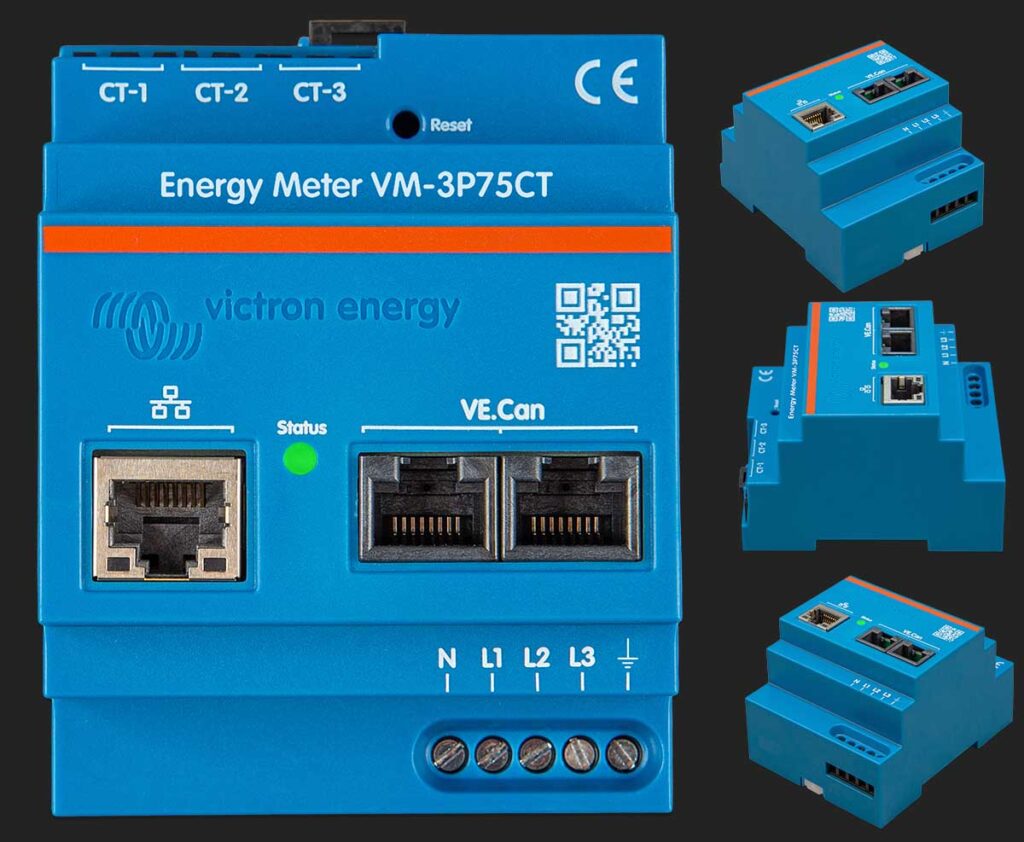
When you open the box of your new Victron VM-3P75CT, you’ll be greeted with the main energy meter unit, which comes with three input terminal blocks. These blocks are your go-to points for connecting the device to your electrical setup.
3x split-core current transformers
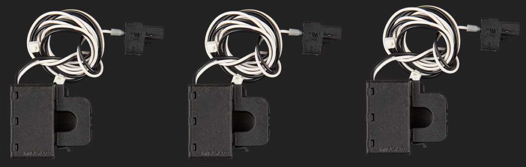
Also nestled within the packaging are three split-core current transformers. These are already wired and prepared for you to connect, making the setup process as seamless as possible.
The transformers feature a generous wire length of 640mm (25.3 inches), giving you flexibility in placement and installation.
2x VE.Can terminators

To complete the setup, you’ll find two VE.Can RJ45 terminators. You’ll use these to cap off the VE.Can network, ensuring clear communication within the system and avoiding any potential disruption from signal reflection.
With everything in hand, you’re all set to install the energy meter, designed for a straightforward setup, ensuring that you can get your system up and running quickly without the hassle of altering existing infrastructure.
Technical Specifications of the Victron VM-3P75CT
Below are the key technical specifications for the Victron VM-3P75CT Energy Meter that detail its voltage and current handling, communication features, as well as environmental tolerances, ensuring you have all the necessary information for a seamless integration into your system.
Voltage Inputs
- Voltage Connection: Direct
- Input Voltage Range L-N: 85 to 265VAC
- Input Voltage Range L-L: 150 to 460VAC
- Frequency: 50/60Hz
Current Inputs
- Current Connection: Via current transformers
- Included Transformers: Wire length 640mm (25.2in)
- Rated Current: 75A
Communication:
- VE.Can Communication Port: Two RJ45 connectors, with VE.Can terminators included
- Ethernet Communication Port: One RJ45 connector, supports Modbus UDP
- Refresh Rate: 100ms
Power Supply
- Type: Self-powered via L1-N
- Switch or Circuit Breaker: Required as a disconnecting device (not included)
- External Fuse: Required in the neutral conductor – 500mA (not included)
- Consumption: 1.45W / 3.1VA
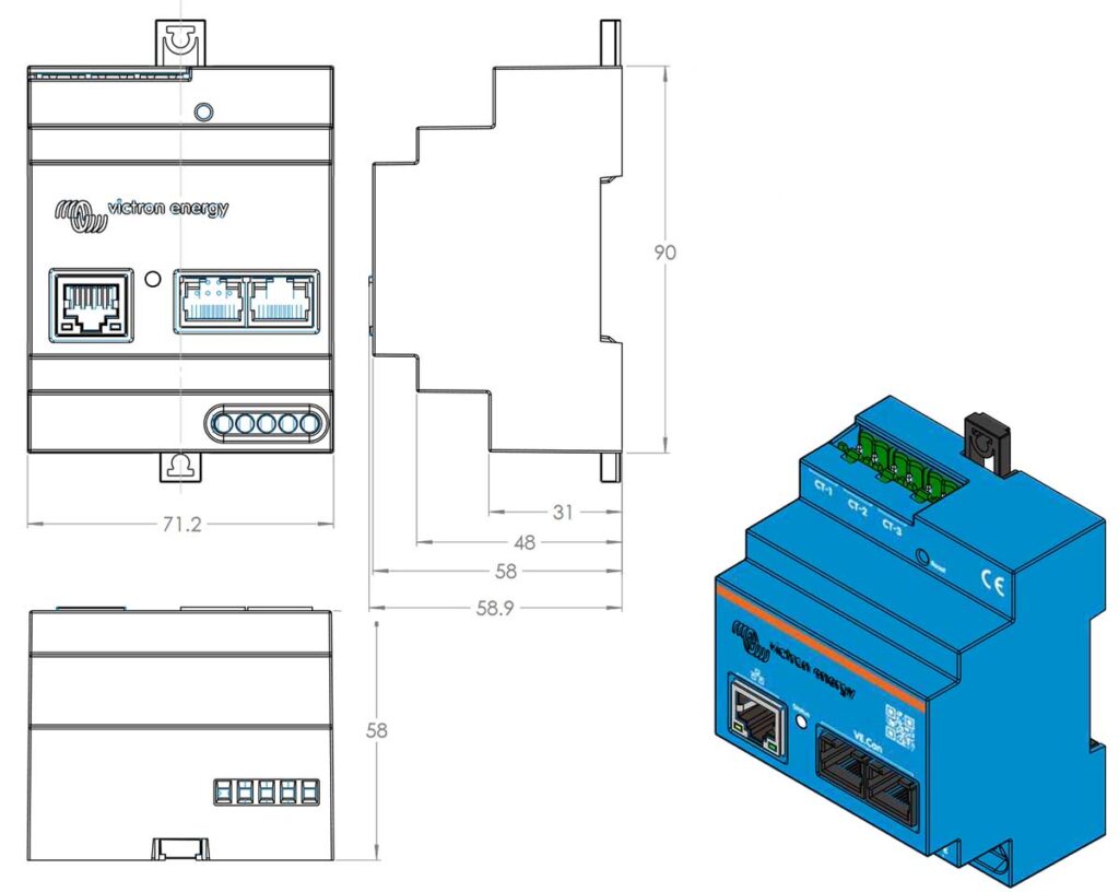
Enclosure
- Material & Color: Polycarbonate, blue (RAL5012)
- Voltage Connection: Screw terminals 0.25 – 1.5mm² (24 – 16AWG)
- Current Transformer Connection: Pluggable screw terminals (included)
- Protection Category: IP20
- Weight: 370g (including packaging)
- Dimensions: 90 x 71 x 59mm (3.5 x 2.8 x 2.3in)
Environmental
- Indoor/Outdoor Usage: Indoor only
- Operating Temperature: From -25 to +55 °C
- Storage Temperature: From -25 to +70 °C
- Relative Humidity: < 90% non-condensing
- Altitude: Up to 2000m (6562ft)
- Mains Supply Voltage Fluctuations: ±0.1Vin
- Overvoltage Category: Cat. II
- Pollution Degree: 2
Standards
- Safety: Complies with EN-IEC 61010-1
NOTE: The external fuse can be omitted if a circuit breaker with a fuse rating of 500mA is used as the isolating device.
These specifications are essential for installation, integration into energy systems, and ensuring compliance with safety and operational standards. When setting up or servicing the VM-3P75CT, it’s crucial to follow these specifications closely to ensure the device operates correctly and safely.
Installing the Victron VM-3P75CT Energy Meter
The installation process of the Victron VM-3P75CT Energy Meter is straightforward and designed for efficiency.
This section will guide you through the necessary steps to ensure your energy meter is correctly installed and set up for accurate monitoring and analysis. From mounting the device to connecting the current transformers, each step is detailed to help you achieve a successful installation.
AC Wiring Instructions
As you begin installing your Victron VM-3P75CT Energy Meter, there are critical guidelines you must follow to ensure safety and maintain the device’s accuracy:
- Never attach the current clamps directly onto bare wires. This is crucial for your safety and the proper functioning of the equipment.
- Handle the current transformers with care. They’re sensitive components and should be installed with the following steps:
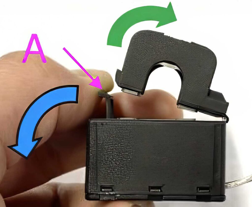
- Start by opening Section A without twisting the head. This part is designed to detach smoothly.
- Once open, securely clamp the head by hand.
- It’s imperative to connect each current transformer to the correct phase wire and corresponding input terminal. They are clearly marked to guide you to the correct port. Remember, these devices are pre-calibrated for accuracy at the factory, and mismatching the connections will compromise this precision.
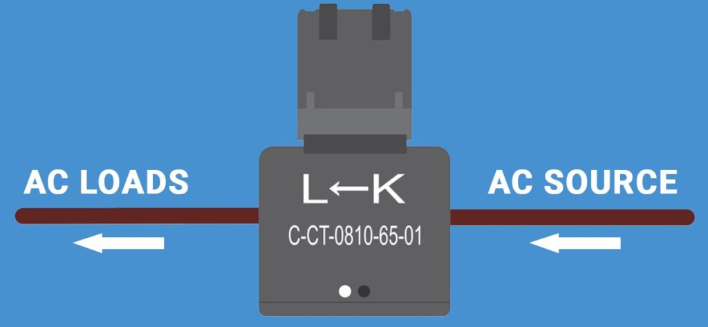
- Look for the arrow on the current transformer labeled “L ← K” and ensure it points towards the load side, not the source.
Check wiring connections
Double-check that all wires are correctly connected to their respective voltage terminals.
Incorrect connections, such as mixing up two phase wires with the neutral and L1 inputs, could cause damage to the meter.
Disconnect for service or maintenance
To safely disconnect the energy meter for service or maintenance, you need either a switch or a 2-pole circuit breaker connecting L1 and Neutral (N).
Additionally, a 500mA fuse should be installed in the neutral conductor unless your circuit breaker already has this rating.
Extending Transformer Wires
- If necessary, you can extend the wires of the current transformers. However, be aware that this may introduce a slight increase in measurement noise.
- As a general rule, longer cables can lead to higher background noise levels, but even if you double the length, the added measurement error is minimal.
- To minimize any induced noise, it’s best to twist the extended wires in the same manner as the pre-supplied wires.
In the event of damage to a split-core transformer, it’s recommended to order a replacement from your Victron dealer. Please note, if you replace a current transformer, the device will need to be recalibrated, as it will no longer retain its factory-set accuracy.
AC Wiring Examples of the Victron VM-3P75CT Energy Meter
Navigating the complexities of AC wiring is made easier with the Victron VM-3P75CT Energy Meter’s versatile design, accommodating various electrical systems.
This subsection presents 5 illustrative wiring setups to guide you through integrating the meter into your specific energy framework.
Whether you’re connecting a three-phase system to the grid, managing a single-phase setup, interfacing with an IT system, measuring AC loads, or monitoring the output from a PV inverter or generator, these examples provide clear and actionable information for each unique scenario.
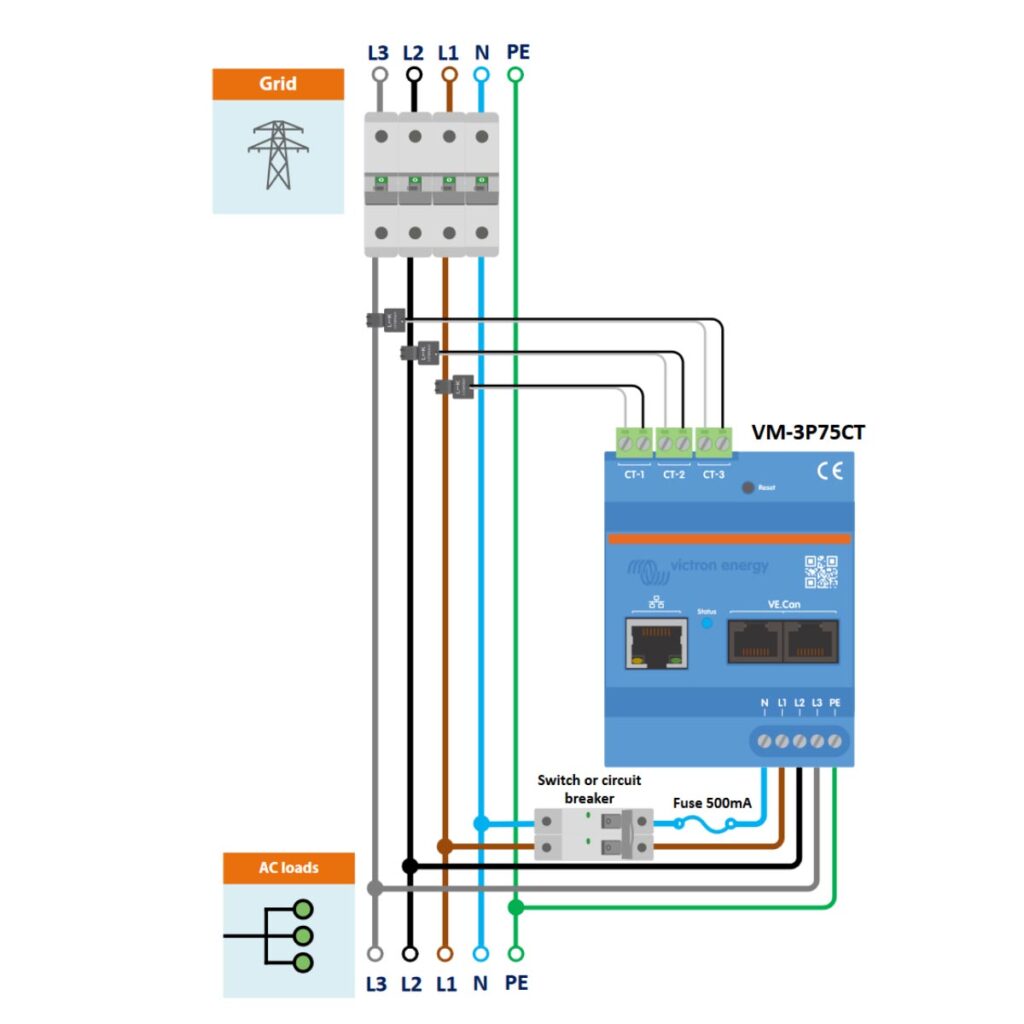
VM-3P75CT 3-Phase Wiring as a Grid Meter
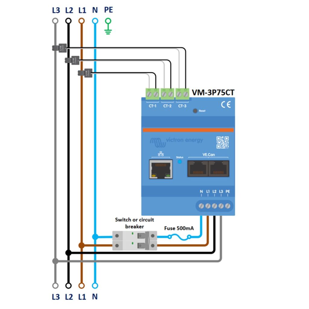
First, let’s take a look at the connection setup when using the VM-3P75CT with a three-phase wiring system, when used as a grid meter to monitor the entire grid supply.
To install the Victron VM-3P75CT Energy Meter in a three-phase system, components such as a 3-phase circuit breaker, current transformers, and protective fuses are required. The procedure includes safely installing these components, ensuring correct connection of phase and neutral cables, and establishing a solid ground connection.
What You’ll Need:
- Victron VM-3P75CT Energy Meter: The main device for monitoring energy usage.
- 500mA Fuse: To protect the meter from potential overcurrent through the neutral conductor.
- Current Transformers: For measuring the electrical current flowing through each phase (L1, L2, L3) of the power system.
- 3-Phase Circuit Breaker: For installation on the incoming L1, L2, L3, and Neutral (N) lines of the incoming grid.
- 1-Phase Switch or Circuit Breaker: For installation on the L1 phase and Neutral (N), after the energy meter.
- Connection Cables for 3-Phase Supply (L1, L2, L3): To connect the meter to each of the three phases for measurement purposes.
- Neutral (N) Cable: For the return path of the current and to complete the circuit for the meter.
- Protective Earth (PE) Cable: For grounding and safety, to protect against electrical shocks and surges.
Step-by-Step Instructions:
- Safety First: Ensure that all power sources are turned off before beginning the installation to prevent any electrical hazards.
- Install 3-Phase Circuit Breaker: Install 3-Phase Circuit Breaker on the L1, L2, L3, and Neutral (N) lines coming from the grid. This will allow you to disconnect both the phase and neutral lines for safe electrical isolation of the meter during maintenance or emergencies.
- Install the Current Transformers (CTs): Place the CT-1, CT-2, and CT-3 around the L1, L2, and L3 phase conductors, respectively. These should be placed after the 3-Phase Circuit Breaker, but before the Energy Meter. Ensure the arrows on the Current Transformers point in the direction of the power flow (towards the load).
- Install 1-Phase Circuit Breaker: Place the single phase circuit breaker on the outgoing L1 line and Neutral (N) from the energy meter. The breaker provides a means to safely disconnect the energy meter and ensures protection during maintenance or in the case of an electrical fault.
- Install Neutral Fuse: Install the 500mA fuse on the outgoing Neutral (N) line from the Energy meter, to protect the energy meter from potential over-current through the neutral conductor. This needs to be positioned between the 1-phase switch/circuit breaker and the energy meter.
- L1, L2, L3 Power Cables: Connect L1 phase cable coming from the grid to the outgoing L1 of the single phase circuit breaker, which then leads to the L1 of the AC Loads. The L2, and L3 phase cables coming from the grid power source should be connected to their corresponding L2, and L3 terminals on the energy meter, before also leading to the L2 and L3 of the AC Loads.
- Neutral (N) cable: Connect the Neutral (N) cable from the grid, to the outgoing Neutral (N) of the single phase circuit breaker.
- Grounding Configuration: Connect the Protective Earth (PE) from both the grid PE and the energy meter’s PE to a common grounding point (such as a bus-bar), then from there to the PE of the AC loads. This ensures a continuous and effective ground path for the entire system.
- Final Inspection:
- Double-check all connections against the provided diagram for accuracy.
- Ensure the fuse and the switch or circuit breaker are installed correctly and functioning.
- Power On and Test:
- After verifying all connections, turn on the power.
- Observe the energy meter’s readings to ensure it is properly recording the energy consumed by the AC loads.
- Documentation and Labeling:
- Label all cables and components for future reference.
- Document the installation setup for troubleshooting or future adjustments.
By following these instructions, your VM-3P75CT will be correctly configured to measure the power consumption from the grid, providing valuable data for energy management and monitoring. Remember to handle all electrical installations with care and consult a professional electrician if necessary.
VM-3P75CT 1-Phase Wiring as a Grid Meter
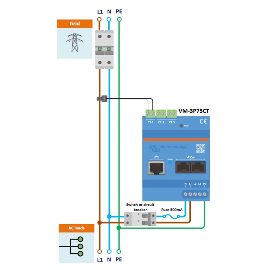
Next, let’s take a look at the connection setup when using the VM-3P75CT with a single-phase supply line (L1) with neutral (N) and protective earth (PE) connected to the energy meter.
To set up the Victron VM-3P75CT Energy Meter as a grid meter in a single-phase system, you’ll need specific components and to follow precise installation steps. The process involves installing a 1-phase circuit breaker and current transformers, connecting power and neutral cables, and ensuring proper grounding.
What You’ll Need:
- Victron VM-3P75CT Energy Meter: The main device for monitoring energy usage.
- 500mA Fuse: To protect the meter from potential overcurrent through the neutral conductor.
- Current Transformer: For measuring the electrical current flowing through L1 (Line One) of the power system.
- 1-Phase Circuit Breaker: For installation on the L1 and Neutral (N) lines of the incoming grid.
- 1-Phase Switch or Circuit Breaker: For installation on the L1 and Neutral (N), after the energy meter.
- Connection Cables for 1-Phase Supply (L1): To connect the meter to the single phase for measurement purposes.
- Neutral (N) Cable: For the return path of the current and to complete the circuit for the meter.
- Protective Earth (PE) Cable: For grounding and safety, to protect against electrical shocks and surges.
Step-by-Step Instructions:
- Safety First: Make sure the power supply is turned off at the main breaker to avoid any risk of electric shock during installation.
- Install 1-Phase Circuit Breaker: Install 1-Phase Circuit Breaker on the L1, and Neutral (N) lines coming from the grid. This breaker will provide a safety disconnect for the entire system, allowing maintenance and ensuring protection in the event of an electrical fault.
- Install the Current Transformers (CTs): Place the CT-1 around the L1 phase conductor. These should be placed after the 1-Phase Circuit Breaker, but before the Energy Meter. Ensure the arrows on the Current Transformer points in the direction of the power flow (towards the load).
- Install 1-Phase Circuit Breaker: Place the single phase circuit breaker on the outgoing L1 line and Neutral (N) from the energy meter. The breaker provides a means to safely disconnect the energy meter and ensures protection during maintenance or in the case of an electrical fault.
- Install Neutral Fuse: Install the 500mA fuse on the outgoing Neutral (N) line from the Energy meter, to protect the energy meter from potential over-current through the neutral conductor. This needs to be positioned between the 1-phase switch/circuit breaker and the energy meter.
- L1 Power Cables: Connect L1 cable coming from the grid to the outgoing L1 of the single phase circuit breaker, which then leads to the L1 of the AC Loads.
- Neutral (N) cable: Connect the Neutral (N) cable from the grid, to the outgoing Neutral (N) of the single phase circuit breaker.
- Grounding Configuration: Connect the Protective Earth (PE) from both the grid PE and the energy meter’s PE to a common grounding point (such as a bus-bar), then from there to the PE of the AC loads. This ensures a continuous and effective ground path for the entire system.
- Final Inspection:
- Review all connections to ensure they match the provided diagram and are secure.
- Confirm that the fuse and the switch or circuit breaker are correctly installed.
- Power On and Test:
- Turn the power back on and observe the energy meter for proper operation.
- Verify that it is correctly measuring the single-phase power consumption.
- Documentation and Labeling:
- Label all connections clearly for future reference.
- Document the installation details for maintenance or troubleshooting purposes.
By following these instructions, your VM-3P75CT will be set up to accurately measure the power consumption from a single-phase grid supply, helping you manage and monitor your energy use effectively. Always ensure that each step is performed with caution, and consult a professional if you have any doubts about the process.
VM-3P75CT 3-Phase IT System Wiring
This configuration is for a three-phase IT system, which is a type of network without a direct connection to the earth and is typically used for enhanced reliability in certain industrial settings.
Here is a forum post on the difference between IT system and a regular 3-phase system.
Besides the difference in earthing, the wiring follows the same basic structure as the standard three-phase wiring with fuses and a switch or circuit breaker for protection and isolation.
What You’ll Need:
- Victron VM-3P75CT Energy Meter: The main device for monitoring energy usage.
- 500mA Fuse: To protect the meter from potential overcurrent through the neutral conductor.
- Current Transformers: For measuring the electrical current flowing through each phase (L1, L2, L3) of the power system
- 1-Phase Circuit Breaker: For installation on the L1 phase and Neutral (N), after the energy meter.
- Connection Cables for 3-Phase Supply (L1, L2, L3): To connect the meter to each of the three phases for measurement purposes.
- Neutral (N) Cable: For the return path of the current and to complete the circuit for the meter.
- Protective Earth (PE) Cable: For grounding and safety, to protect against electrical shocks and surges.
Step-by-Step Instructions:
- Safety First: Start by turning off the power source to prevent any electrical shock or accidents during the installation.
- Install the Current Transformers (CTs): Place the CT-1, CT-2, and CT-3 around the L1, L2, and L3 phase conductors, before the Energy Meter, respectively. Ensure the arrows on the CTs point in the direction of the power flow (towards the load).
- Install Neutral (N) Fuse: Install the 500mA fuse on the outgoing Neutral (N) line from the Energy meter, to protect the energy meter from potential overcurrent through the neutral conductor. This needs to be positioned between the 1-phase switch/circuit breaker and the energy meter.
- Install 1-Phase Circuit Breaker: Place the single phase circuit breaker on the outgoing L1 line and Neutral (N) from the energy meter. The breaker provides a means to safely disconnect the energy meter and ensures protection during maintenance or in the case of an electrical fault.
- L1, L2, L3 Power Cables: Connect L1 phase cable coming from the grid to the outgoing L1 of the single phase circuit breaker, which then leads to the L1 of the AC Loads. The L2, and L3 phase cables coming from the grid power source should be connected to their corresponding L2, and L3 terminals on the energy meter, before also leading to the L2 and L3 of the AC Loads.
- Neutral (N) cable: Connect the Neutral (N) cable from the grid, to the outgoing Neutral (N) of the single phase circuit breaker.
- Grounding Configuration: In an IT system, the grounding or Protective Earth (PE) is not connected to the energy meter. Instead, it should be connected to the earth grounding system within your installation setup.
- Final Inspection:
- Carefully inspect all connections to ensure they’re accurate and secure.
- Confirm the correct installation of the fuse and the switch or circuit breaker.
- Power On and Test:
- Once all connections have been double-checked, restore the power.
- Check the energy meter’s readings to make sure it is correctly tracking the power usage.
- Documentation and Labeling:
- Clearly label all the connections for future reference and maintenance.
- Document your installation setup in detail for any future troubleshooting or audits.
IMPORTANT: When dealing with an IT system, particular attention should be paid to the grounding system and how it is integrated with the meter and the overall electrical setup. IT systems have specific requirements that differ from TN and TT systems, particularly concerning fault conditions and the handling of over-current protection.
By following these steps, your VM-3P75CT will be properly wired to measure electrical parameters in a 3-phase IT system. If you have any hesitations or need further assistance, consult with a professional electrician familiar with IT systems or reach out to Victron for support.
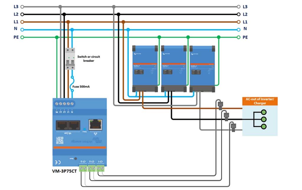
VM-3P75CT 3-Phase Wiring to Measure AC Loads
The meter in this setup is specifically wired to measure the power consumption of AC loads.
- The three-phase lines, neutral, and protective earth are routed through the meter to the AC loads.
- The fuse and switch/circuit breaker are present as in the general wiring examples for protection and maintenance isolation.
What You’ll Need:
- Victron VM-3P75CT Energy Meter: The main device for monitoring energy usage.
- 500mA Fuse: To protect the meter from potential over-current through the neutral conductor.
- 3x Inverter/Charger Units
- Current Transformers: For measuring the electrical current flowing through each phase (L1, L2, L3) of the power system
- 1-Phase Circuit Breaker: For installation on the L1 phase and Neutral (N), after the energy meter.
- Connection Cables for 3-Phase Supply (L1, L2, L3): To connect the meter to each of the three phases for measurement purposes.
- Neutral (N) Cable: For the return path of the current and to complete the circuit for the meter.
- Protective Earth (PE) Cable: For grounding and safety, to protect against electrical shocks and surges.
Step-by-Step Instructions:
- Install 1-Phase Circuit Breaker: Place the single phase circuit breaker on the outgoing L1 line and Neutral (N) from the energy meter. The breaker provides a means to safely disconnect the energy meter and ensures protection during maintenance or in the case of an electrical fault.
- Install Neutral (N) Fuse: Install the 500mA fuse on the outgoing Neutral (N) line from the Energy meter, to protect the energy meter from potential over-current through the neutral conductor. This needs to be positioned between the 1-phase switch/circuit breaker and the energy meter.
- Connect L1 Power cables:
- Connect the L1 phase cable coming from the grid power source to the outgoing L1 of the 1-Phase circuit breaker.
- From the outgoing L1 of the 1-Phase circuit breaker, connect a L1 phase cable to the AC-In of the 1st Inverter/Charger.
- Then connect a L1 phase cable from the AC-Out of the first Inverter/Charger to the L1 AC-In of the Loads.
- Connect L2 Power cables:
- Connect the L2 phase cable coming from the grid power source to the AC-In of the 2nd Inverter/Charger.
- Then connect the L2 phase cable from the AC-Out of the 2nd Inverter/Charger to the L2 AC-In of the Loads.
- Connect L3 Power cables:
- Connect the L3 phase cable coming from the grid power source to the AC-In of the 3rd Inverter/Charger.
- Then connect the L3 phase cable from the AC-Out of the 3rd Inverter/Charger to the L3 AC-In of the Loads.
- Install the Current Transformers (CTs):
- Place the CT-1, CT-2, and CT-3 around the L1, L2, and L3 phase conductors, respectively, just before the AC-In of the Loads (between the loads and the inverter/chargers).
- Ensure the arrows on the Current Transformers point in the direction of the power flow (towards the load).
- Neutral (N) cables:
- Connect the Neutral (N) cable coming from the grid power source to the outgoing Neutral (N) of the 1-Phase circuit breaker.
- From the outgoing Neutral (N) of the 1-Phase circuit breaker, connect a Neutral (N) cable to the Neutral (N) AC-In on each of the three separate Inverter/Chargers
- This connects to the three inverters in a parallel configuration. Each inverter receives a neutral line from the same branching point, which allows them to operate independently of each other while being part of the same electrical system
- Connect PE (Protective Earth) Cables:
- Connect this PE wire from the grid supply, directly to the PE terminal on the Victron VM-3P75CT Energy Meter. This connection grounds the energy meter and is essential for safety, providing a path for fault currents and preventing electrical shock.
- From the PE terminal on the Energy Meter, run separate PE cables to each of the three inverter/chargers, connecting it to their Primary chassis ground connection M6 (PE). Refer to the invert’s manual to locate this terminal.
- Note that this is different from the AC-In PE ground. Here is an explanation on the Difference between the AC-In PE ground and Primary PE ground on Multiplus II for clarification
- Each inverter/charger should have its own PE cable running back to the PE terminal on the Energy Meter, either directly or via an earthing bus-bar.
- Ensure that each Inverter/Charger has a PE wire connected from its grounding terminal to the corresponding grounding terminal at the AC Loads. This may involve running a PE wire from the inverter/charger to a central grounding point or busbar that is then connected to the AC Loads.
- Final Inspection:
- Carefully inspect all connections against the diagram to ensure they match the specified configuration.
- Verify that the fuse and the switch or circuit breaker are correctly installed and functional.
- Power On and Test:
- Once you have checked and ensured all connections are correct, restore the power.
- Monitor the energy meter to confirm it is accurately measuring the AC load consumption.
- Documentation and Labeling:
- Clearly label all connections and safety devices for future reference.
- Note down your configuration in case you need to perform troubleshooting or future modifications
By following these detailed steps, your VM-3P75CT should be correctly set up to measure your AC loads. Always ensure that each step is completed with precision, and if there are any uncertainties, consult a professional electrician or Victron’s technical support.
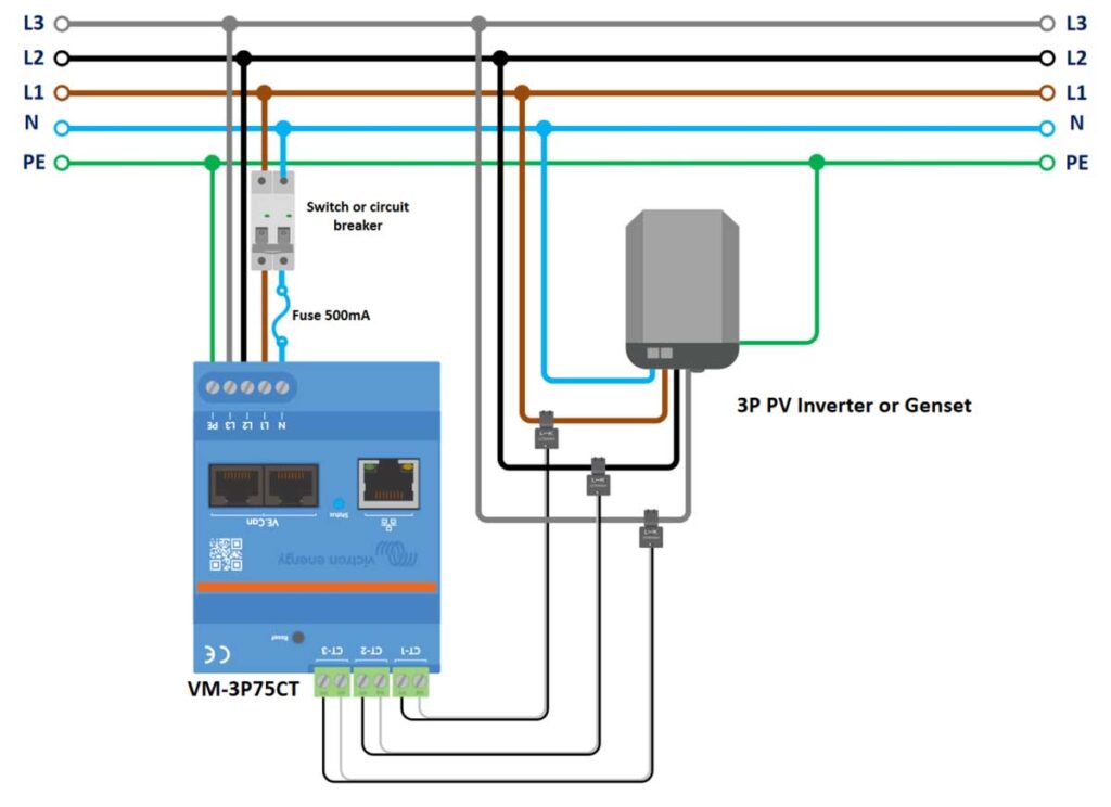
VM-3P75CT 3-Phase Wiring to Measure a PV Inverter or Generator
In this scenario, the meter is used to measure the output of a three-phase PV inverter or generator. The wiring from the PV inverter or generator’s AC output is connected to the meter.
What You’ll Need:
- Victron VM-3P75CT Energy Meter: The main device for monitoring energy usage.
- 500mA Fuse: To protect the meter from potential over-current through the neutral conductor.
- PV Inverter or Generator:
- Current Transformers: For measuring the electrical current flowing through each phase (L1, L2, L3) of the power system
- 1-Phase Circuit Breaker: For installation on the L1 phase and Neutral (N), after the energy meter.
- Connection Cables for 3-Phase Supply (L1, L2, L3): To connect the meter to each of the three phases for measurement purposes.
- Neutral (N) Cable: For the return path of the current and to complete the circuit for the meter.
- Protective Earth (PE) Cable: For grounding and safety, to protect against electrical shocks and surges.
Step-by-Step Instructions:
- Safety First: Ensure all power sources are turned off. This step is crucial to prevent electrical accidents.
- Install 1-Phase Circuit Breaker: Place the single phase circuit breaker on the outgoing L1 and Neutral (N) from the energy meter. The breaker provides a means to safely disconnect the energy meter and ensures protection during maintenance or in the case of an electrical fault.
- Install Neutral (N) Fuse: Install the 500mA fuse on the outgoing Neutral (N) line from the Energy meter, to protect the energy meter from potential overcurrent through the neutral conductor. This needs to be positioned between the 1-phase switch/circuit breaker and the energy meter.
- Connect L1 (brown) Power cables:
- Connect the L1 phase cable coming from the grid power source to the outgoing L1 of the 1-Phase circuit breaker.
- From the outgoing L1 of the 1-Phase circuit breaker, connect a L1 phase cable to the L1 AC-In of the 3-Phase PV inverter or Genset.
- Connect L2 (black) Power cables:
- Connect the L2 phase cable coming from the grid power source to the L2 AC-In of the 3-Phase PV inverter or Genset.
- Connect L3 (gray) Power cables:
- Connect the L3 phase cable coming from the grid power source to the L3 AC-In of the 3-Phase PV inverter or Genset.
- Install the Current Transformers (CTs):
- Place the CT-1, CT-2, and CT-3 around the L1, L2, and L3 phase conductors, respectively, just before the AC-In of the 3-Phase PV inverter or Genset.
- Ensure the arrows on the Current Transformers point in the direction of the power flow (towards the load).
- Neutral (N) cables:
- Connect the Neutral (N) cable coming from the grid power source to the outgoing Neutral (N) of the 1-Phase circuit breaker.
- From the outgoing Neutral (N) of the 1-Phase circuit breaker, connect another Neutral (N) cable to the Neutral (N) AC-In of the 3-Phase PV inverter or Genset.
- Connect PE (Protective Earth) Cables:
- Connect this PE wire from the grid supply, directly to the PE terminal on the Victron VM-3P75CT Energy Meter. This connection grounds the energy meter and is essential for safety, providing a path for fault currents and preventing electrical shock.
- From the PE terminal on the Energy Meter, run a separate PE cable to the 3-Phase PV inverter or Genset’s primary chassis ground connection (PE). Refer to the invert’s manual to locate this terminal.
- Final Inspection:
- Carefully inspect all connections against the diagram to ensure they match the specified configuration.
- Verify that the fuse and the switch or circuit breaker are correctly installed and functional.
- Power On and Test:
- Once you have checked and ensured all connections are correct, restore the power.
- Monitor the energy meter to confirm it is accurately measuring the AC load consumption.
- Documentation and Labeling:
- Clearly label all connections and safety devices for future reference.
- Note down your configuration in case you need to perform troubleshooting or future modifications.
By carefully following these instructions, your VM-3P75CT will be properly set up to monitor the output from a 3-phase PV Inverter or Generator, ensuring accurate measurement for your energy management system. Always proceed with caution and consult a professional if needed.
Ethernet and VE.Can wiring of the Victron VM-3P75CT Energy Meter
For establishing robust and reliable data communication, the Victron VM-3P75CT Energy Meter features Ethernet and VE.Can connectivity options.
This section delves into the specifics of wiring your energy meter using these interfaces. You’ll learn how to leverage the Ethernet for network integration and the VE.Can ports for direct device communication, ensuring your energy meter is fully connected for optimal performance and monitoring.
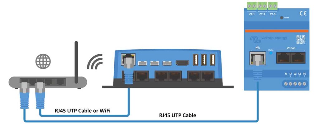
Connecting the VM-3P75CT to the GX Device via Ethernet
Let’s take a look at how to connect the Victron VM-3P75CT Energy Meter to a GX device using an Ethernet connection, to ensure effective communication between the energy meter and the GX device for optimal monitoring and control.
What You’ll Need:
- Victron VM-3P75CT Energy Meter.
- GX device (like Cerbo GX).
- RJ45 UTP Ethernet Cable.
- Access to a local network, router, or direct Ethernet connection to the GX device.
Step-by-Step Instructions:
- Network Configuration: If your GX device is already connected to the local network via Ethernet or Wi-Fi, ensure it’s functioning correctly and has network access.
- Cable Connection: Use an RJ45 UTP Ethernet cable to connect the VM-3P75CT’s Ethernet port to an available port on your router or directly to the GX device if it’s not already connected to the network.
- Power On and Configure:
- Once connected, power on the VM-3P75CT and the GX device.
- Access the GX device’s interface to configure the energy meter. You might need to set the IP address or allow the device to obtain one automatically via DHCP.
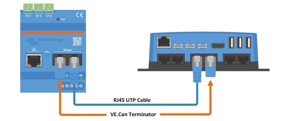
Connecting the VM-3P75CT to the GX Device via VE.Can
Let’s take a look at how to connect the Victron VM-3P75CT Energy Meter to a GX device using a VE.Can connection for similar results as the Ethernet connection.
What You’ll Need:
- Victron VM-3P75CT Energy Meter.
- GX device (like Cerbo GX).
- RJ45 UTP Cable for VE.Can connection.
- VE.Can terminators.
Step-by-Step Instructions:
- Direct Connection: Instead of using the local network, you’re making a direct connection between the energy meter and the GX device.
- Cable Connection: Connect one end of the RJ45 UTP cable to the VE.Can port on the VM-3P75CT and the other end to the VE.Can port on the GX device.
- Terminating the VE.Can Network: Attach the VE.Can terminators at both ends of the VE.Can network. This is important to prevent signal reflections which could disrupt communication.
- Power On and Configure:
- Power on both the VM-3P75CT and the GX device.
- Enter the GX device’s interface and ensure the VE.Can network sees the energy meter and is correctly configured for communication.
For both methods, using good quality Ethernet cables, such as the ones provided by Victron, is recommended to ensure reliable communication. Different lengths are available to suit various installation needs.
Configuration & Monitoring of the VM-3P75CT via VictronConnect
Moving forward from the Ethernet and VE.Can wiring setup, this section focuses on the configuration of the Victron VM-3P75CT Energy Meter using VictronConnect for both direct and remote connections, highlighting how to navigate through the app for real-time data monitoring and detailed configuration settings.
Finally, we take a look at how to monitor the energy meter through the GX device interface.
Initial Setup and Connection Options:
- Connecting to GX Device: Connect the VM-3P75CT to a GX device using one of two methods:
- VE.Can Connection: Connect the VM-3P75CT directly to the GX device’s VE.Can port. Ensure proper termination of the VE.Can network with the provided VE.Can terminators for signal integrity.
- Ethernet Connection: Use an RJ45 UTP Ethernet cable to connect the VM-3P75CT to the local network, where the GX device is also connected, either via Ethernet or Wi-Fi.
- Device Detection:
- VE.Can: The VM-3P75CT will be automatically detected by the GX device upon connection and termination.
- Ethernet: The VM-3P75CT periodically broadcasts mDNS packets, which allow the GX device to automatically discover the meter on the local network.
Configuration via VictronConnect:
- Accessing VictronConnect:
- Launch VictronConnect on your mobile device, laptop, or PC.
- Ensure you are connected to the same local network for a direct connection, or configure for remote access via VC-R if the GX device is connected to the VRM Portal.
- VictronConnect Setup: Within VictronConnect, connect to the VM-3P75CT:
- Connect Directly via Ethernet using Modbus/UDP on the local network.
- Connect Remotely via VictronConnect-Remote, accessible through VE.Can or Modbus/UDP.
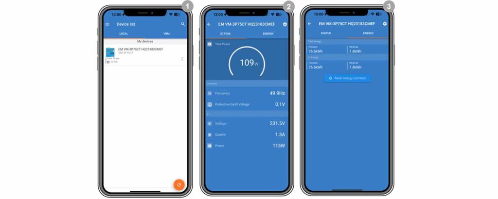
- Monitoring Data:
- Instant Readout: The VM-3P75CT provides Instant Readout of key metrics such as total power and power per phase, accessible from the Device list in VictronConnect.
- Detailed data display is split between:
- Status Page: Real-time phase-specific measurements.
- Energy Page: Cumulative energy data production and consumption.
Detailed Configuration Settings:
To access the Meter Settings, go into the VictronConnect app, then:
- Go to the ‘Device list‘
- Select the “VM-3P75CT” device
- Tap on the cogwheel icon for settings.
Here you will see the following setup options:
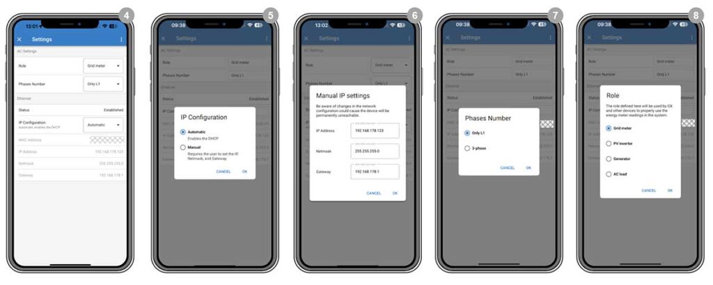
- Role: Choose the appropriate role for the VM-3P75CT (Grid, Inverter, Generator, or AC Meter) based on the measurement application.
- Phase Configuration: Select ‘Only L1’ for a single-phase setup or ‘3-phase’ for a three-phase system.
- IP Configuration: Typically, leave IP configuration to ‘Automatic’ (DHCP) for the meter to receive an IP address dynamically.
- Use ‘Manual’ configuration only if a static IP address is required by your network setup. Enter the IP address, netmask, and gateway as provided by your network administrator.
Once you have configured the Role, Phase Number, and IP Configuration, the setup of the VM-3P75CT is complete.
- The meter will now communicate with the GX device, providing data for monitoring and analysis via VictronConnect.
- No additional configuration is required on the GX device other than ensuring the Modbus TCP/UDP option is enabled for the VM-3P75CT.
GX Device Monitoring for VM-3P75CT:
To properly monitor the VM-3P75CT through a GX device (such as the Cerbo GX or Ekrano GX), it’s essential to activate it within the GX device’s system.
Here’s a detailed guide using the information you’ve provided:
- Establish Connection: Ensure that the VM-3P75CT is connected to the GX device via the local network, either through an Ethernet or VE.Can connection.
- Access GX Device Interface: Navigate to the GX device’s interface. This can typically be done via a web browser or a dedicated interface on the device itself.
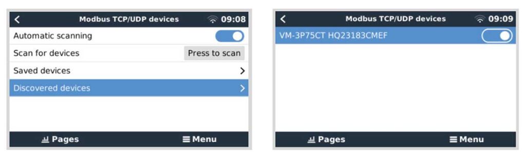
- Activate the Energy Meter: Once in the GX device interface, follow this path to activate the VM-3P75CT:
- Go to Settings.
- Select Modbus TCP/UDP devices.
- Under Discovered devices, find the VM-3P75CT. It may be listed by its serial number or model identifier.
- Toggle the switch next to the VM-3P75CT to enable it. By default, the device is disabled when first installed and must be manually activated to be monitored.
Accessing the Device List:
Once the Victron VM-3P75CT Energy Meter is activated and connected to the GX device, you can monitor and manage it directly from the GX device’s interface. Here’s how you can navigate the GX device interface and what you can do once the VM-3P75CT is detected and listed.
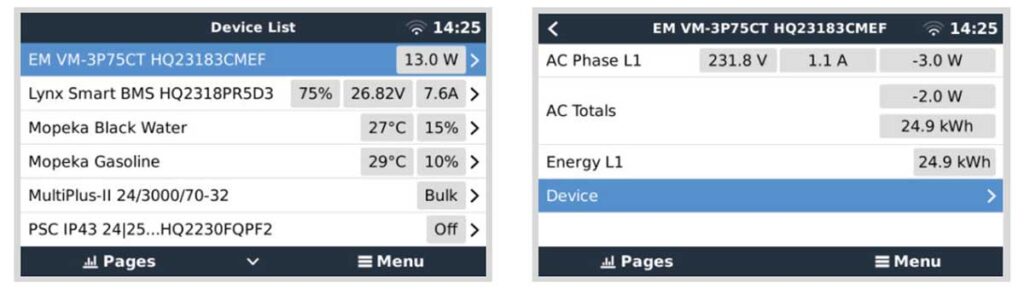
- Device List Display:
- Upon successful activation, the VM-3P75CT will appear in the GX device’s ‘Device List’.
- This list is accessible through the GX device interface, which you can usually enter via a web browser or a dedicated screen if your model has one.
- Device Overview Page:
- A right-click (or a long press on touch devices) on the VM-3P75CT entry in the ‘Device List’ will bring up the device overview page.
- This page displays current data for each individual phase, including AC totals and total energy per phase.
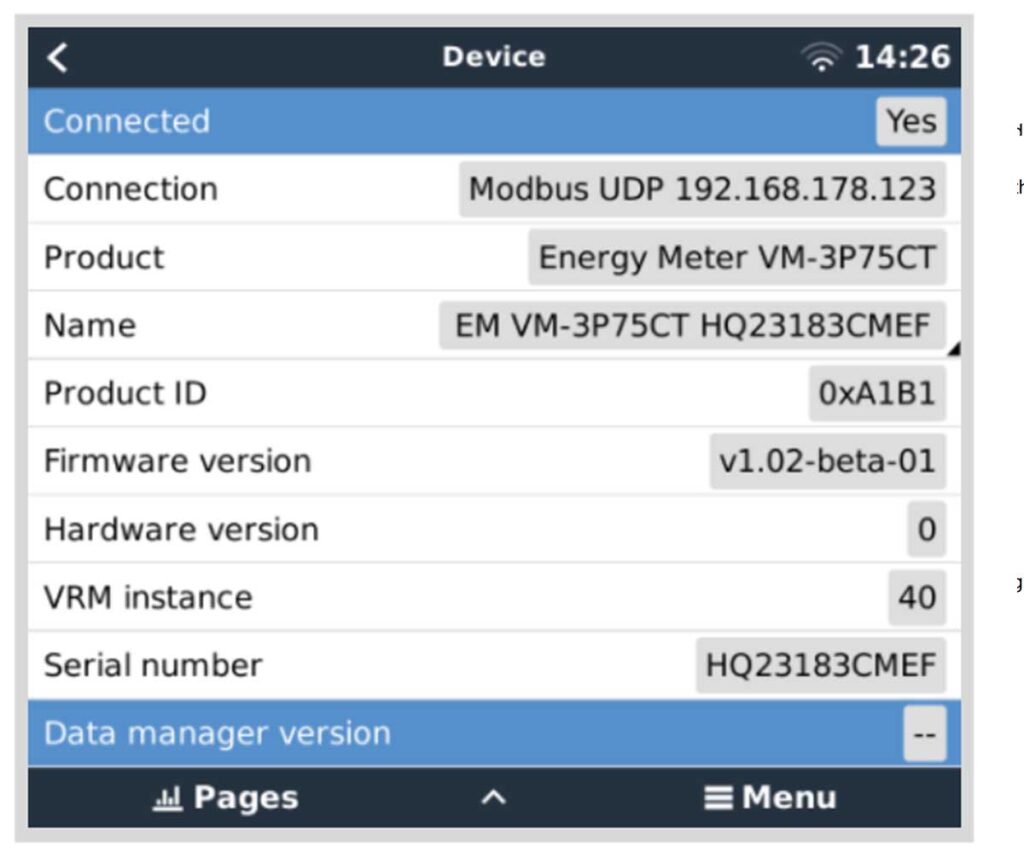
- Device Page:
- The ‘Device’ page provides a comprehensive overview of the connection status and hardware-specific data such as the product ID, firmware version, hardware version, and more.
- Here, you can also assign a custom name to the energy meter, which can be helpful for easy identification, especially if you’re managing multiple devices.
By following these steps, you can effectively monitor and manage the VM-3P75CT from the GX device interface.
Remember that the detailed information and control offered by the GX device and VictronConnect software give you a powerful toolset for overseeing your energy system’s performance.
LED Codes & Errors of the VM-3P75CT Energy Meter
The Victron VM-3P75CT Energy Meter comes with an LED indicator that provides valuable information about the device’s status and helps diagnose issues.
Below are the LED codes and their meanings, as well as troubleshooting steps for specific behaviors.
LED Codes and Their Meanings:
- Blinking Fast Alternately Green/Red: The device is in bootloader/update mode. This typically indicates a firmware update is in progress.
- Solid Green: Normal operating mode; the device is functioning correctly.
- Blinking Green @ 1Hz (50% duty cycle): This is the unit’s identify mode, making it easier to identify which unit you are interacting with in a multi-device setup. It stops automatically after 60 seconds.
- Off for 3 Seconds, On for Another 10 Seconds: This pattern occurs when you press the reset button for about 15 seconds. It indicates that the device is resetting to factory defaults.
- Off and Immediately On After a Brief Button Press: A quick press and release of the reset button will restart the device.
- Solid Red: This indicates an error with the device.
Troubleshooting LED Behaviors:
Firmware Update Modes:
- If the LED is blinking fast alternately green/red, wait for the firmware update to complete. The LED should turn solid green once the update finishes.
- If the update is unsuccessful or if the device has no application to start, it will remain in bootloader mode. In this case, you will need to reattempt the firmware update using VictronConnect locally via Ethernet or WiFi, or remotely using VRM, as bootloader mode does not support VC-R for updates.
Error Codes:
- 116 – Calibration Data Lost: If this error occurs and the device is non-functional, contact your dealer for a replacement.
- 119 – Settings Corrupt: If the energy meter cannot read its configuration and has stopped, perform a factory reset as described in the manual.
- 122 – kWh Counters Corrupt: To correct this error, reset the kWh counter.
For all error codes, the VM-3P75CT will also display an error code on connected GX devices, VRM, and within VictronConnect, providing a more detailed explanation of the issue.
Factory reset the VM-3P75CT Energy Meter
To reset the Victron VM-3P75CT Energy Meter to factory defaults or to restart the device, you have two methods available: using the recessed RESET button on the device or through the VictronConnect app.
Restarting the Energy Meter
To restart the energy meter, briefly press the recessed RESET button on the device.
- The LED indicator on the energy meter will turn off and then immediately turn back on, indicating that the device has restarted.
Resetting to Factory Defaults
If you are experiencing a major issue in accordance with the LED lights, then it is often best to factory reset the VM-3P75CT Energy Meter. Here is how to do that.
Using the RESET Button
- Initiate Reset: Press and hold the RESET button. The LED will turn off for about 3 seconds.
- Continue Holding: Keep pressing the button for another ~10 seconds. The LED will turn off again.
- Complete Reset: Release the button after this period, and the device will restart with factory default settings, including:
- IP configuration set to Automatic (DHCP).
- Role set to Grid.
- Phase configuration set to 3-phase.
- Custom name reverted to “VM-3P75CT” followed by the serial number.
Using the VictronConnect App
- Access VictronConnect: Open the VictronConnect app on your compatible device and select the energy meter you wish to reset from the device list.
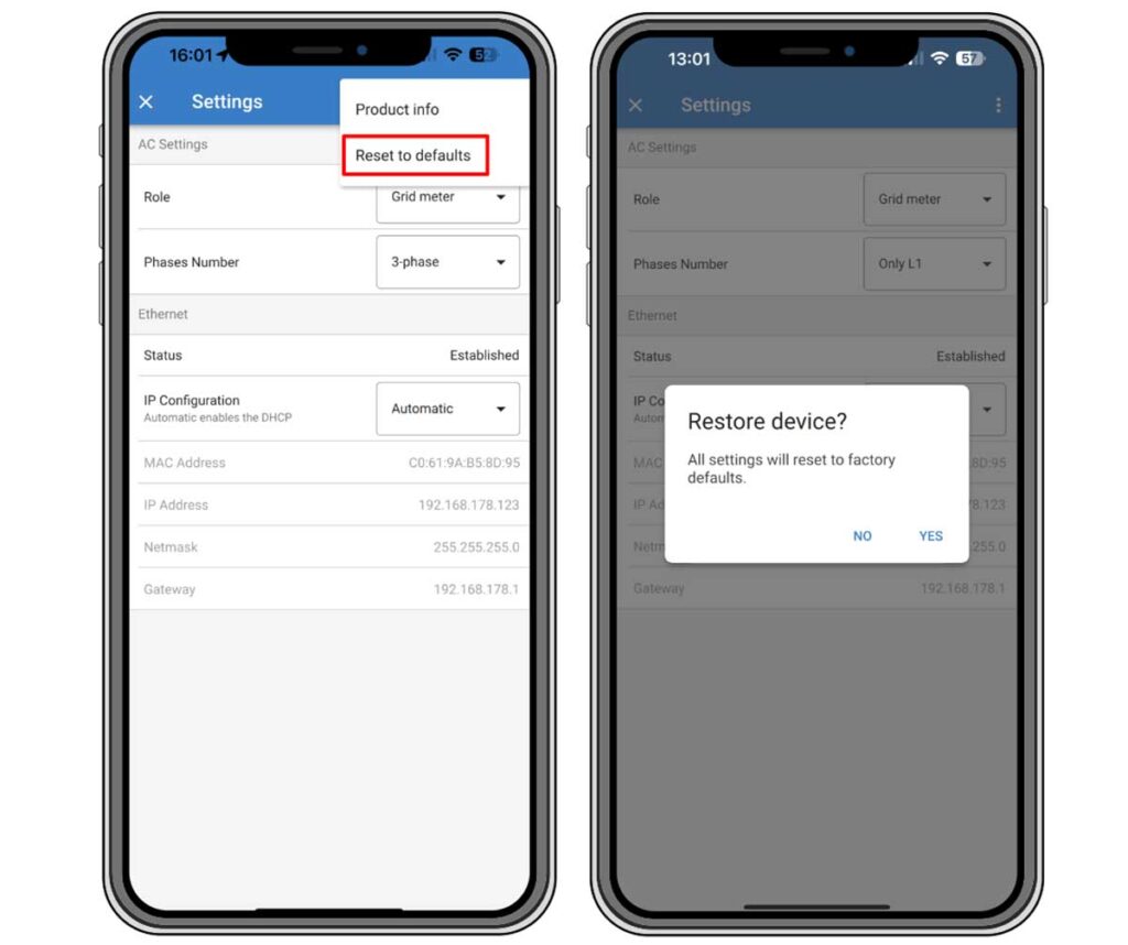
- Enter Settings: Tap the gear icon on the status page to access the settings page.
- Navigate to Reset Option: Tap the three vertical dots at the top right corner of the settings page to open a pop-up menu.
- Reset to Defaults: Choose ‘Reset to defaults’ from the pop-up menu.
- Confirm Reset: A confirmation pop-up will appear. Confirm the reset process by tapping on “YES”.
Post-Reset Configuration:
- After the energy meter has been reset to factory defaults, you may need to reconfigure it if the default settings do not suit your system’s requirements. This can include setting a static IP address, changing the device role, or adjusting phase configuration settings.
- To reconfigure the device, refer to the chapter “Configuration & Monitoring” in the Victron VM-3P75CT Energy Meter Manual, and follow the guidelines provided for your specific system setup.
This process ensures that you can quickly restore your VM-3P75CT Energy Meter to its original factory settings and reconfigure it as needed for optimal performance within your energy system.
Update Firmware of Victron VM-3P75CT Energy Meter
Updating the firmware of the Victron VM-3P75CT Energy Meter is a crucial process to ensure the device runs efficiently with the latest features and security updates.
Methods for Firmware Update
There are 3 methods of updating the firmware of the Victron VM-3P75CT Energy Meter.
VRM (Victron Remote Management): Remote Firmware Update
- This method allows for updating the firmware remotely and works for both Ethernet and VE.Can connections.
- To perform the update, the energy meter and the GX device must be connected to the VRM Portal.
- The firmware update is initiated through the VRM Portal’s interface, which will push the update to the energy meter.
VictronConnect-Remote (VC-R):
- Similar to VRM, VC-R allows for remote updates over Ethernet and VE.Can connections.
- You will need to access VictronConnect and use the remote update feature within the app to send the firmware to the energy meter.
VictronConnect Locally via Ethernet/WiFi:
- For a local update, the energy meter needs to be on the same local network as the device running VictronConnect.
- Connect to the energy meter through the VictronConnect app and follow the prompts within the app to complete the firmware update process.
Steps for Firmware Update Using VictronConnect Locally:
- Ensure Local Network Connectivity: Verify that both the energy meter and your device running VictronConnect are connected to the same local network.
- Open VictronConnect: Launch the VictronConnect app on your device.
- Select the Energy Meter: Choose the VM-3P75CT from the list of devices within the app.
- Initiate Firmware Update: Follow the in-app instructions to start the firmware update process. The app will typically have an ‘Update’ button if an update is available.
- Complete the Update: Wait for the firmware update to download and install. Do not interrupt the power supply to the energy meter during the update.
Important Notes:
- It is recommended to ensure the energy meter is connected to a stable power source throughout the update process.
- The device should remain connected to the network without interruption.
- After the update, it is good practice to verify that the energy meter restarts and functions correctly.
By following these methods, you can successfully update the firmware of the Victron VM-3P75CT Energy Meter, thereby ensuring that your device benefits from the latest improvements and features provided by Victron Energy. Always refer to the official Victron documentation for detailed instructions and support.
Understanding Power in AC Systems when using the Victron VM-3P75CT Energy Meter
Discrepancy between the power value displayed and the current value is a common issue related to power factor in AC electrical systems.
Here’s an explanation to clarify the situation:
- Active (Real) Power (P): The active power is what is actually consumed by the loads to do work. It is measured in Watts (W) and is calculated as the product of voltage (V), current (I), and the power factor (cos(θ)).
- Apparent Power (S): Apparent power is the product of the root mean square (RMS) voltage and current. It is measured in Volt-Amps (VA) and represents the total power flow in the system.
- Power Factor (cos(θ)): The power factor is the ratio of active power to apparent power and indicates how effectively the electricity is being used. A power factor of 1 (or unity) means all the power is effectively used for work. However, most systems have a power factor less than 1 due to the presence of inductive or capacitive loads, leading to reactive power.
- Reactive Power: Reactive power does not perform any work but is necessary to sustain the electromagnetic fields in inductive and capacitive loads. It is measured in reactive volt-amperes (VAR).
High Apparent Power vs. Real Power:
- In cases where you see high current values with lower active power readings, it’s typically because of a low power factor. This means there is a significant amount of reactive power in the system.
- Devices like USB chargers, LED lights, and some types of renewable energy equipment can have poor power factors, thus widening the gap between apparent and real power.
Solutions for Poor Power Factor:
- Power Factor Correction Equipment: Installing power factor correction devices can help improve the power factor of your system, thus bringing the apparent power closer to the real power value.
- Better Power Factor Loads: Opt for devices and appliances with a better power factor. Many modern devices, especially those with switch mode power supplies like personal computers, often include power factor correction features.
- Consult a Professional: If power factor issues are significantly affecting your system, it may be wise to consult with an electrical engineer who can provide tailored solutions, such as the installation of power factor correction capacitors or other devices.
In summary, it is normal to observe a higher apparent power compared to real power in an AC system, especially when inductive or capacitive loads are present. If this causes concern or inefficiencies in your system, seeking power factor correction solutions is recommended.
Conclusion of the VM-3P75CT Energy Meter
In conclusion, the Victron VM-3P75CT Energy Meter emerges as a comprehensive solution for diverse energy management needs, suitable for both single and three-phase applications.
The VM-3P75CT’s advanced features, such as its capacity to measure high currents, compatibility with multiple communication protocols, and ease of installation with split-core current transformers, make it an ideal choice for various applications, including solar PV systems, AC generators, and inverter/chargers.
With this knowledge, you can now effectively install, configure, and utilize the Victron VM-3P75CT Energy Meter in your energy system, to optimize your energy management and monitoring.
Should you have any further questions or need insights from fellow users, feel free to join the discussion and seek guidance on the Victron VM-3P75CT Energy Meter Community forum, for sharing experiences and resolving queries related to the VM-3P75CT Energy Meter.