MultiPlus-II 230V Connection Overview
MultiPlus-II 3000VA (3kVA) & 5000VA (5kVA)
Here is the Connection Overview for the Victron Multiplus-II 230V 3000VA & 5000VA models:
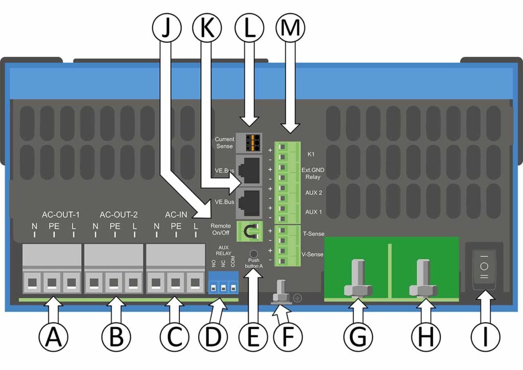
| A | Load connection. AC out1. Left to right: N (neutral), PE (earth/ground), L (phase) |
| B | Load connection. AC out2. Left to right: N (neutral), PE (earth/ground), L (phase) |
| C | AC input: Left to right: N (neutral), PE (earth/ground), L (phase) |
| D | Alarm contact: (left to right) NO, NC, COM. |
| E | Push button A – To perform a startup without assistants. |
| F | Primary ground connection M6 (PE). |
| G | Size M8 (8mm) battery positive connection. |
| H | Size M8 (8mm) battery minus connection. |
| I | switch: 1=On, 0=Off, ||=charger only |
| J | Connector for remote switch: Short to switch “on”. |
| K | 2x RJ45 VE-BUS connector for remote control and/or parallel / three-phase operation |
| L | External current sensor To connect the current sensor; remove the wire bridge between the INT and COM terminals, connect the red sensor wire to the EXT terminal and connect the white sensor wire to the COM terminal. To connect the current sensor; remove the wire bridge between the INT and COM terminals, connect the red sensor wire to the EXT terminal and connect the white sensor wire to the COM terminal. |
| M | Terminal for: top to bottom: M1: 12V 100mA M2: Programmable contact K1 open collector 70V 100mA M3: External ground relay + M4: External ground relay – M5: Aux input 1 + M6: Aux input 1 – M7: Aux input 2 + M8: Aux input 2 – M9: Temperature sense + M10: Temperature sense – M11: Battery voltage sense + M12: Battery voltage sense – |
MultiPlus-II 8000VA (8kVA), 10000VA (10kVA) & 15000VA (15kVA)
Here is the Connection Overview for the Victron Multiplus-II 230V 8000VA (8kVA), 10000VA (10kVA) & 15000VA (15kVA) models:
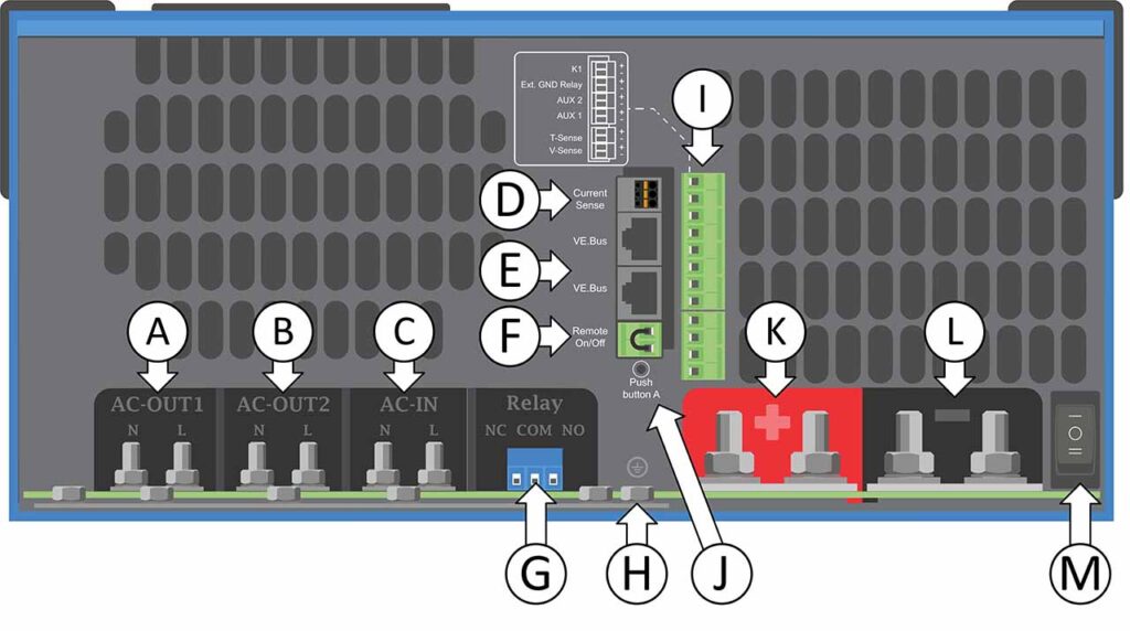
| A | Load connection. AC out 1. Left to right: N (neutral) and L (phase). |
| B | Load connection. AC out 2. Left to right: N (neutral) and L (phase). |
| C | AC input: Left to right: N (neutral) and L (phase). |
| D | External current sensor.To connect the current sensor; remove the wire bridge between the INT and COM terminals, connect the red sensor wire to the EXT terminal and connect the white sensor wire to the COM terminal. |
| E | 2x RJ45 VE-BUS connector for remote control and/or parallel / three-phase operation. |
| F | Connector for remote on/off switch: Short to switch “on”. |
| G | Alarm contact: (left to right) NO, NC, COM. |
| H | Earth/ground busbar for both AC input PE, AC output PE and chassis earth/ground M6 connections. |
| I | Terminal for: top to bottom: 12V 100mA Programmable contact K1 open collector 70V 100mA External ground relay + External ground relay – Aux input 1 + Aux input 1 – Aux input 2 + Aux input 2 – Temperature sense + Temperature sense – Battery voltage sense + Battery voltage sense – |
| J | Push button A – To perform a startup without assistants. |
| K | M8 battery positive connection. |
| L | M8 battery minus connection. |
| M | Main switch: 1=On, 0=Off, ||=charger only |